We are extremely pleased to report that a preprototype device consisting of a single exposure cell was successfully produced and finally assembled in June of 2021.
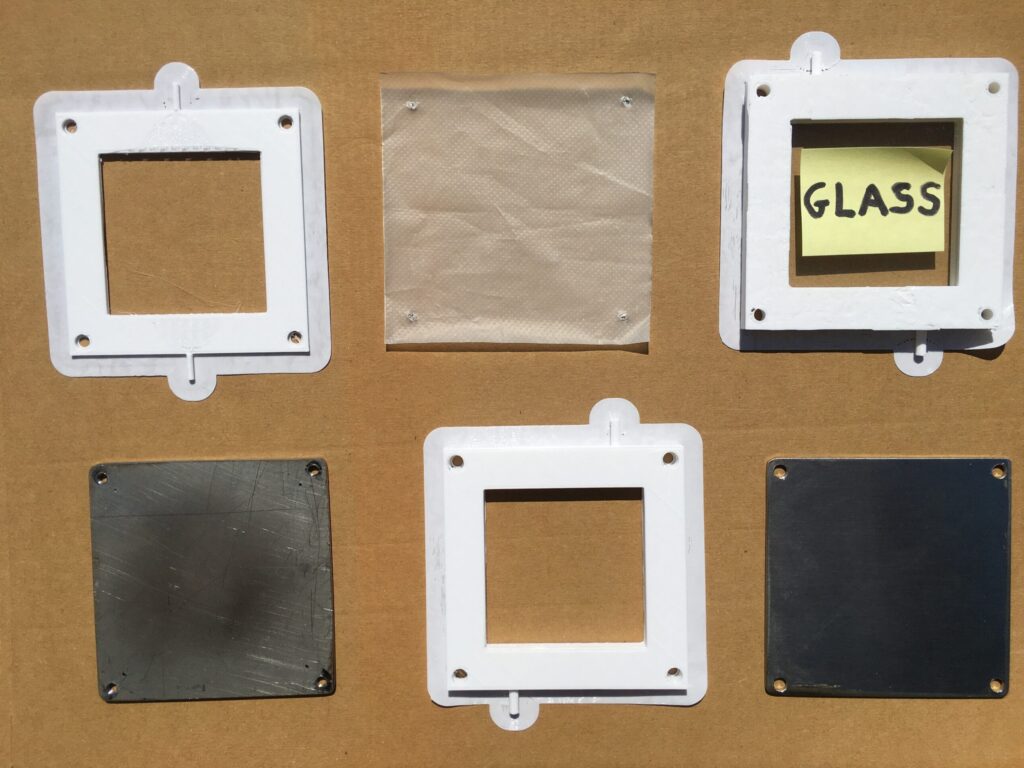
The concept in creating the single cell exposure cell preprototype was based on a stackable design of eight individual layers.
In going from bottom to top, the layers are as follows.
Layer No. 1: The metal “base plate”. Dimensions are 9 cm x 9 cm. This is the thicker one with no polishing necessary. There is a hole in each of the four corners, and all four holes are tapped for 8-32 bolts.
Layer No. 2: The “cooling plenum”. Dimensions are 9 cm x 9 cm. It has two ports, with one as an input port and the other as an output port. There is a hole in each of the four corners.
Layer No. 3: The “second metal plate”. Dimensions are 9 cm x 9 cm. This is the thinner one, with the dull side down (facing the cooling plenum) and with the highly-polished side up (facing the blood plenum). There is a hole in each of the four corners.
Layer No. 4: The “blood plenum”. Dimensions are 9 cm x 9 cm. It has two ports, with one as an input port and the other as an output port. This layer has a very complicated internal design which allows for the “channelling” of the blood, so that it transitions from being a circular cross-section to that of a flattened out and thin rectangular cross-section. This transition occurs both for the blood entering the plenum, and by using a mirrored internal design, for the blood exiting the plenum. There is a hole in each of the four corners.
Layer No. 5: The “semipermeable membrane”. Dimensions are 9 cm x 9 cm for an exact fit, or 10 cm x 10 cm allowing for a 0.5 cm “overhang” around the perimeter. The actual prototype is expected to consist of PTFE coated with a biocompatible polymer that faces the blood plenum. The preprototype simply has a piece of very thin plastic to “simulate” the PTFE. There is a hole in each of the four corners.
Layer No. 6: The “oxygen gas plenum”. Dimensions are 9 cm x 9 cm. It has two ports, with one as an input port and the other as an output port. The upper portion of this layer has a 1.5 mm “recessed zone” for the lower half of the 3 mm piece of glass to set into. There is a hole in each of the four corners.
Layer No. 7: The “piece of glass”. Dimensions are 7 cm x 7 cm. A piece of common window glass with a thickness of 3 mm is used to simulate a high-quality quartz-based optical window, the type of which is used in sophisticated laser optics The piece of glass becomes ‘sandwiched’ between Layer No. 6 and Layer No. 8.
Layer No 8: The “upper bracket”. Dimensions are 9 cm x 9 cm. The lower portion of this layer has a 1.5 mm “recessed zone” for the upper half of the 3 mm piece of glass to fit into. Therefore, the peripheral area of Layer No. 8 sets directly on top of the peripheral area of Layer No. 6. There is a hole in each of the four corners.
Other than Layer No. 7 (the piece of glass) which has no holes, the holes in each of the four corners for all of the other layers vertically align upon stacking the layers together.
Layer No. 1 (metal base plate), Layer No. 3 (second metal plate), Layer No. 5 (semipermeable membrane), and Layer No. 7 (piece of glass) are all solid pieces without any central “cut-out areas”. However, Layer No. 2 (coolant plenum), Layer No. 4 (blood plenum), Layer No. 6 (oxygen gas plenum), and Layer No. 8 (upper bracket) all have a 6 cm x 6 cm central “cut out”.
Four 8-32 bolts, with one in each corner, are used to compress all eight layers together, along with standard washers for Layer No. 8, and lock washers and nuts under Layer No. 1, the base plate.
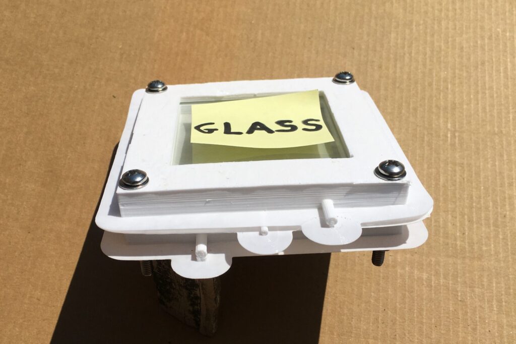
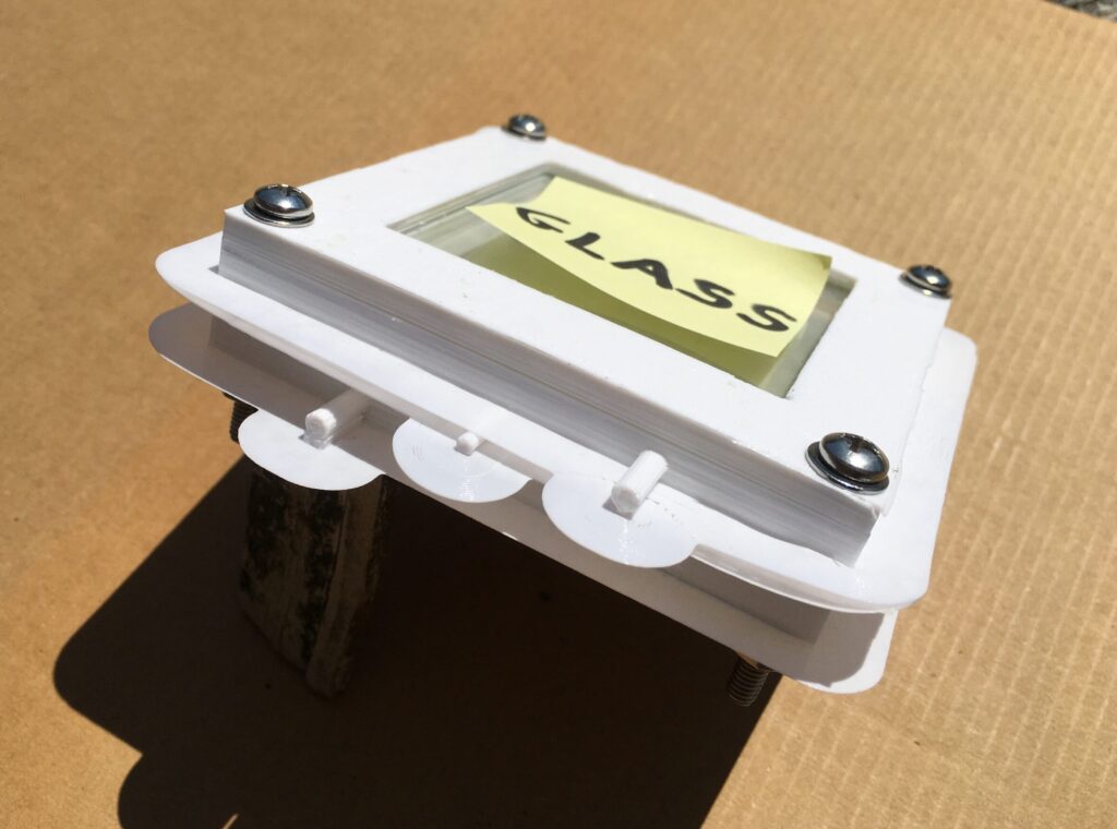
After many months of multiple iterations and refinements using the three-dimensional computer-aided design platform of SolidWorks, along with an integrated 3D Printer technology, four of the eight stackable layers were recently printed in durable plastic.
The Upper Right Component Depicted Consists of the Stacked Top Three Layers.

The Input Port and Output Port for Layer 2 and Layer 6 are Diagonally Opposed.
The Input Port and Output Port for Layer 4 are Directly Opposed.
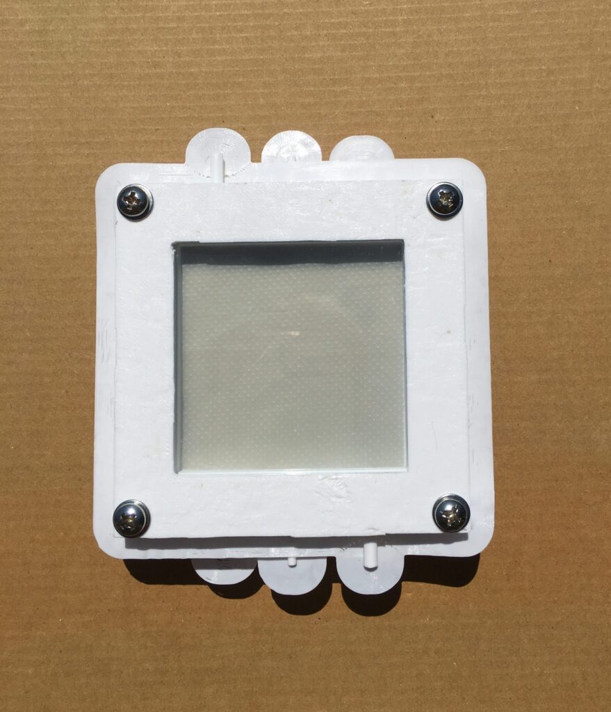
Simulated Semipermeable Membrane Visible Through Glass Optical Window.
The design and assembly of the single exposure cell preprototype clearly demonstrates “proof of principle” for the construction of the subsequent prototype.
Design of the actual prototype reaction chamber has been underway. This reaction chamber will consist of either a pentagonal or hexagonal array of either five or six identical exposure cells. Modifications are naturally required for the input and output ports, which at this point are considered proprietary.